



Please Leave Us A Message
Privacy statement: Your privacy is very important to Us. Our company promises not to disclose your personal information to any external company with out your explicit permission.

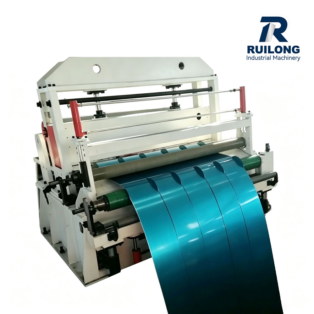
Record only what you would act on, and group it so a fault can be traced backwards. Five groups cover it. Anything that would not change a decision does not belong, because a sheet nobody fills in is worse than no sheet at all.
| Group | Fields | What it lets you do |
| Job identity | Coil number, grade, mill-certificate tensile, gauge, target widths | Separate a material problem from a setup problem |
| Tooling identity | Knife set ID, actual ground OD, spacer set, regrind count | Trace a bad edge to a specific set |
| Settings | Clearance in mm, overlap in mm, torque figure, spacer stack | Repeat the job without re-deriving it |
| Measurements | Burr, rollover, width on three strips, camber | Prove the first piece before running |
| The omitted one | Slitter drive current at test cut, line speed at test cut | Trend knife wear without stopping the line |
Two fields in that table are routinely left blank and cost the most when they are. The ground outside diameter after each regrind matters because overlap is set from the centre distance, and every regrind removes material on radius — a set that has been ground twice without the stack being re-measured is running an overlap you did not set. The drive current matters because it is the only wear signal available while the line is running, and it needs no instrument beyond the one already on the drive. Ruilong reviews both fields at commissioning and adds them to the sheet before handover.
✅ Bottom line: if a field would not change what you do next, cut it — the sheet earns its keep by being filled in completely on every job.
Build it offline, load it in a fixed order, verify clearance physically, then gate the first piece on measurements. Ruilong runs the whole sequence at the customer's factory during commissioning rather than describing it in a manual. How to assemble a slitter gang step by step matters because the most common setup failures are mechanical, not numerical: a thin spacer cocked on the shaft, a chip between two faces, or a clamp nut tightened by feel.
The assembly order that tooling specialists converge on runs as follows:
The slitting line first piece inspection checklist before production is the gate at that point, and it is short:
Only then accelerate in steps — 25%, 50%, 75%, 100% — watching tension at each stage. Ruilong runs this gate as part of commissioning and hands the sheet over with the line.
✅ Bottom line: assemble offline, torque to the figure rather than past it, and never release the first piece on appearance alone — four measurements and one current reading take under five minutes.
Q: What does a slitting line setup sheet template what to record actually need on it? A: Five groups — job identity, tooling identity with the ground OD, settings in millimetres, first-piece measurements, and drive current at the test cut. Anything that would not change a decision is a field that will be left blank.
Q: How to assemble a slitter gang step by step without a tooling room? A: A bench-mounted spare shaft matching your arbor diameter, a dial indicator arm and a torque wrench cover it. Build the next job while the current coil runs; that single change is worth 15–20 minutes per changeover and costs almost nothing.
Q: What goes on a slitting line first piece inspection checklist before production release? A: Burr against the percentage limit for the grade, width on two or three strips, edge appearance with a check for a second burnish band, camber against the downstream requirement, and drive current logged against the job baseline.
Send Ruilong your grades, gauge range and typical strip pattern. As a slitting line manufacturer in China, Tai'an Ruilong Machinery Co., Ltd. supplies a custom setup sheet and first-piece gate for your jobs, ships the matched OEM/ODM tooling with a pre-sorted spacer set and an offline assembly mandrel, and quotes factory-direct — one supplier accountable from the tooling room to the first coil.

October 25, 2026
October 24, 2026
Email to this supplier
October 25, 2026
October 24, 2026
Privacy statement: Your privacy is very important to Us. Our company promises not to disclose your personal information to any external company with out your explicit permission.
Fill in more information so that we can get in touch with you faster
Privacy statement: Your privacy is very important to Us. Our company promises not to disclose your personal information to any external company with out your explicit permission.